Description
NE555-Blue:
- Onboard NE555 IC.
- Single channel signal output, the output duty cycle about 50% square wave.
- Plate load resistor, adjust the resistance to control the output frequency.
- Onboard power indicator.
- Working voltage: 5V~12V.
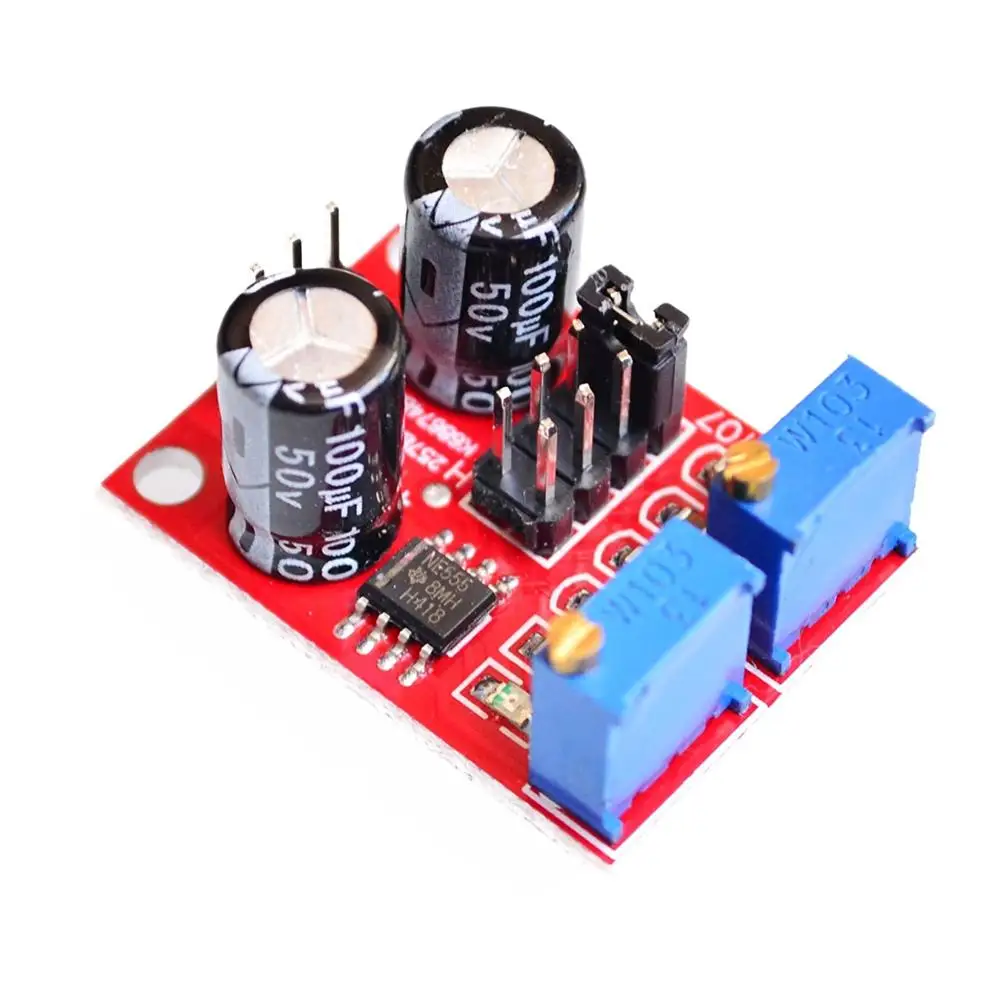
NE555-Red:
1, Size: 3.1CM * 2.2CM
1, the main chip: NE555;
2, Input voltage: 5V-15VDC. 5V power supply, the output current can 15MA around; 12V power supply, the output current can 35MA around;
3, the input current: 100MA
4, the output amplitude: 4.2V V-PP to 11.4V V-PP. (Different depending on the input voltage, the output amplitude will be different)
5, the maximum output current: 15MA (5V power supply, V-PP greater than 50%), 35MA (12V power supply, V-PP greater than 50%)
The scope of this module:
1 is used as a square wave signal generator generates a square wave signal used for experimental development.
2 to drive a stepper motor for generating a square wave drive signal.
3 adjustable pulse generated for use by MCU.
4 adjustable pulse generation, control circuitry associated.
Advantages:
1, the output with LED indication, there is no output straightforward (low LED volume, high LED off frequency is relatively low, the LED flashes);
2, the output level selectable frequency range, the output frequency is more continuously adjustable;
LF file: 1Hz ~ 50Hz
IF file: 50Hz ~ 1kHz
High-frequency file: 1KHz ~ 10kHz
HF file: 10kHz ~ 200kHz
3, the output duty cycle can fine-tune, duty cycle and frequency is not separately adjustable, adjusting the duty cycle will change the frequency
4, the output frequency is adjustable;
Period T = 0.7 (RA +2 RB) C
RA, RB is 0-10K adjustable;
Low profile when C = 0.001UF;
IF stalls C = 0.1UF;
High-frequency file C = 1UF;
HF stalls C = 100UF, so the frequency of the waveform buyers can own calculations
NE555-Black:
Functional description:
1. The output side outputs a square wave signal after power is applied, and the amplitude is approximately equal to the power supply voltage.
2. The output frequency is adjustable, and the output voltage is stable during the frequency adjustment.
3 adjustable frequency range, 20HZ-10KHZ according to the need to choose (frequency allows 10% deviation), if you need special frequency need to replace the C1 capacitor.
4. The frequency adjustment is adjusted by the built-in multi-turn potentiometer.
5. Power supply: The power supply voltage is DC 5V-15V and the no-load current is about 3mA.
6. Output drive current: 200mA MAX.
7. Purpose: Use as a signal source in the circuit.
Instructions:
1. Connect to the power supply to work.
2. When used, a 0.1uf power filter capacitor can be connected to the power supply for stable operation.
3. Adjust the potentiometer clockwise, increase the frequency, and adjust the potentiometer counterclockwise to decrease the frequency.
NE555-Upgraded version:
Application scope:
1. Used as a square wave signal generator produces a square wave signal for the experimental development use.
2. A square wave signal is used to produce a stepper motor-driven drive.
3. Produce the adjustable pulse for MCU use.
4. Generates the adjustable pulse to control the associated circuits.
Descriptions:
1. The main chip: LM358.
2. Input voltage: 5V-12VDC.
3. The input current: ≥ 100MA.
4. The output amplitude: close to the input voltage.
5. The frequency adjustment range: 0.07HZ-2KHZ (also cycle in about 0.45ms to 15s).
6. Duty cycle adjustment range: 0% to 100% (High / cycle).
7. Output Current: strip 9012 transistor drive capability is strong, about 500MA output current, the output can directly drive small relays or small motors.
8.Size: 31mm x 11mm x 23mm/1.21″ x 0.43″ x 0.89″ (inch) (approx)
Frequency adjustment methods:
1. The board has four the shorting cap can select the frequency.
2. Inserted 0 short-circuit cap, the longest cycle upwards to 0.3 s.
3. Inserted one short-circuit cap, the longest cycle can be adjusted to about 4s.
4. Inserted two short-circuit cap, the longest cycle can be adjusted to about 7s.
5. Inserted three short-circuit cap, the longest cycle can be adjusted to about 10s.
6. Inserted four short-circuit cap, the longest cycle can be adjusted to about 15s.
7. Duty cycle adjustment range: 0% to 100% (High / cycle).
8. Output Current: strip 9012 transistor drive capability is strong, about 500MA output current, the output can directly drive small relays or small motors.


d***a –
Prishol fast good vrodavets
Color: NE555-Blue
3***r –
View-as in the picture, everything is safe, the pins are not bent.
Color: NE555-Upgraded
A***o –
Everything is fine, the quality is good, it works. Recommend!
Color: NE555-Black
AliExpress Shopper –
Fast delivery, well packed in anti static envelope. Works as mentioned.
Color: NE555-Red
2***r –
All norms. Marking is read, packing is factory, thank you!
Color: NE555-Red
r***r –
The parcel received quickly, everything corresponds to the description, the track was tracked, for all 5 stars,
Many thanks to the seller
Color: NE555-Red
J***a –
All came well packed, checked everything works, the seller recommend
Color: NE555-Black
J***r –
Bought in promotion. 19 days Valencia, Spain. (holidays included)
Color: NE555-Red
P***l –
Color: NE555-Blue